Technology Never Stands Still—and Neither Do We
Validated Mini-ITX platforms engineered for reliable deployment in industrial, edge, and embedded system environments.
Power delivery is one of the most critical aspects of designing Mini‑ITX systems, especially in space-constrained or thermally challenged environments. Unlike full-sized boards, Mini‑ITX platforms pack high-power CPUs and discrete GPUs into tight layouts, making robust power distribution and thermal control difficult but essential.
This guide walks through all the core considerations: VRM design, PSU compatibility, transient management, DC integration, and BIOS power features—giving hardware professionals the insights needed to build reliable, high-performance Mini‑ITX platforms for both consumer and industrial applications.
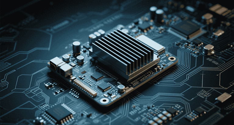
Mini‑ITX motherboards measure 170 × 170 mm. While this allows for flexibility in compact chassis, it drastically reduces space for power delivery circuitry.
Modern CPUs (e.g. AMD Ryzen 7, Intel i7) draw 65–105 W TDP nominally, but peak boost events may require 130–160 W for short durations. This demands that VRMs not only match the CPU spec, but also tolerate transients gracefully.
PCIe slots supply 75 W. For higher-end GPUs (RTX 4060 and above), supplemental power must be delivered via 6- or 8-pin cables. Start-up spikes may hit 150–200 W briefly.
Efficient voltage regulation requires careful selection of MOSFETs, chokes, and capacitors. Many high-end boards use 6+2 or 8+2 phase designs.
| Board Type | VRM Phase | Cooling Method |
|---|---|---|
| Entry Mini‑ITX | 4+1 | Passive heatsink |
| Gaming Mini‑ITX | 6+2 | Active airflow |
| Industrial Thin ITX | 3+1 | Heatsink + pad |
“Thermal behavior of the VRMs is the #1 limiting factor in Mini‑ITX stability during stress testing.” — BuildLogs.net
Common Mini‑ITX PSU choices include SFX, SFX-L, Flex‑ATX, and PicoPSU solutions. When choosing a PSU:
Boot-time failures are common in builds using PicoPSU or low-current bricks. Reasons include:
Solutions:
Safe power transmission depends on cable quality:
| Cable Type | Current Rating | Use Case |
|---|---|---|
| 18 AWG | Up to 7 A | Standard PSU cables |
| 16 AWG | Up to 10 A | High-load GPU cables |
| 24 AWG | <3 A | Avoid for power paths |
Do not share CPU and GPU loads on one cable; isolate power rails for heat and EMI safety.
DDR5 memory and PCIe Gen 4 SSDs can draw significant power. ECC DIMMs increase draw due to constant parity correction.
Industrial systems commonly use DC input ranging from 9–36 V, often in mobile or field installations.
Design Tip: Use TVS diodes + bulk capacitor (470–1000 μF) near DC barrel to suppress surges.
ATX12VO eliminates 3.3 V/5 V rails from PSU, placing more burden on the motherboard to regulate those lines internally.
Implementation requires BIOS/firmware to manage sequencing and Power-Good signals per Intel spec.
Power control is increasingly managed via BIOS or firmware:
Software tools like HWInfo (Windows) and lm-sensors (Linux) help validate thermal and power stability. Some embedded boards offer IPMI/BMC out-of-band monitoring.
Sample Load Calculation:
CPU:   105 W
GPU:   160 W
SSD:    10 W
USB-C:  40 W
VRM loss: 20 W
Total: ≈335 W
→ Recommend 500 W SFX PSU (Gold/Platinum)
By engineering for robust power delivery—across PCB, cabling, VRM, and PSU—you build systems that can thrive in SFF or embedded conditions without compromise.