Technology Never Stands Still—and Neither Do We
Validated Mini-ITX platforms engineered for reliable deployment in industrial, edge, and embedded system environments.
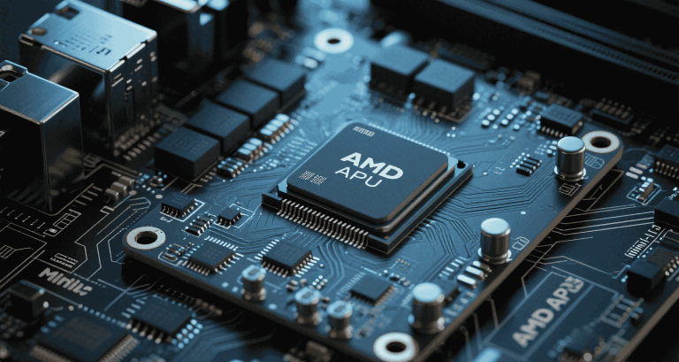
When building high-performance Mini‑ITX systems, the **Voltage Regulator Module (VRM)** is often the critical—but overlooked—determinant of stability. Especially in thermally constrained environments, VRM design affects everything from CPU overclocking to 24/7 embedded uptime.
This article explores Mini‑ITX VRM considerations with a focus on real-world integration challenges, thermal layout trade-offs, component choices, and long-term reliability. Whether you’re designing fanless embedded systems or power-dense desktop builds, the VRM must be a deliberate engineering decision—not an afterthought.
VRMs regulate 12 V input into lower voltage rails for CPUs (Vcore), SoCs, and memory controllers. In high-current CPUs, power quality is directly tied to VRM efficiency, ripple control, and transient response. For Mini‑ITX systems, these factors are intensified by space, thermal, and routing constraints.
Boards vary by VRM phase configuration:
| Board Type | VRM Phases | Target CPUs |
|---|---|---|
| Entry A520I / H610I | 4+1 | i3 / Ryzen 3–5 |
| Mid X670E‑I / B650I | 6+2 | Ryzen 7 / Intel i5 |
| Flagship Z790‑I | 10+2 | Ryzen 9 / Intel i9 |
Higher phase count reduces per-phase heat and improves voltage regulation. However, more phases require complex routing, often constrained in Mini‑ITX PCBs with only 4–6 layers.
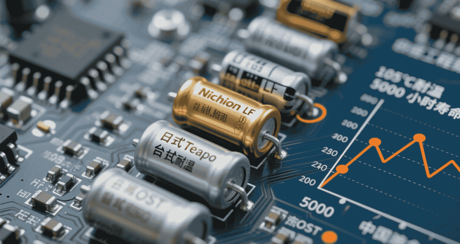
High-quality VRMs use:
“Capacitor degradation in ITX VRMs was the root cause of two thermal shutdowns we investigated in our field systems.” — Integrator Note
Heatsink choice dramatically affects VRM lifespan. Budget boards use thin aluminum or simple extrusions, while premium boards add:
Community tests confirm some Mini‑ITX boards exceed 100 °C VRM temps without airflow—especially under synthetic load.
Good boards expose VRM data via:
Lower-end boards often lack monitoring, forcing engineers to estimate thermal conditions via external IR tools.
Oversized VRM heatsinks may block:
Boards like the MSI B650I Edge include aggressive shrouds that clash with many SFF enclosures—requiring cable rerouting or fan removal.
Mini‑ITX designs often place high-speed lanes (PCIe, USB4) adjacent to VRMs. Without shielding and ground isolation, engineers report issues such as:
“Our inferencing edge node failed QA due to cross-talk between switching VRMs and CSI camera bus.” — Embedded Design Lead
Fanless or 24/7 systems must consider derating VRMs by 10–20% for longevity. Additional recommendations:
| Feature | Budget ITX | Premium ITX |
|---|---|---|
| Phases | 4–5 | 8–12 |
| MOSFETs | Discrete (≤40 A) | Smart Power Stage (≥60–100 A) |
| Cooling | Basic passive | Heatpipe + fin array |
| Sensor Support | None or limited | Full VRM telemetry |
| Fan Headers | 1–2 | 3–4 + VRM fan header |
Ideal VRM zones should stay below 80–85 °C in ventilated Mini‑ITX setups.
Target System:
Ryzen 9 7900X
→ TDP: 105 W (peak ~150 W)
Recommended: 8+2 phase, 60 A DrMOS, copper heatsinks
Case: Meshlicious or NR200
PSU: 650 W SFX Gold
By prioritizing VRM quality and thermal design, hardware engineers can ensure long-term reliability—even in tightly packed Mini‑ITX systems. Boards from trusted brands with strong community validation help avoid surprises in thermally aggressive deployments.