Technology Never Stands Still—and Neither Do We
Validated Mini-ITX platforms engineered for reliable deployment in industrial, edge, and embedded system environments.
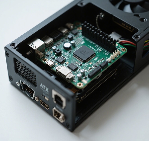
As embedded system designers and hardware engineers, you’re often expected to deliver high-performance solutions in space-constrained environments. Occasionally, you may consider unconventional combinations—such as using a Micro-ATX motherboard inside a Mini-ITX enclosure—to save costs or leverage existing parts. However, this approach can introduce significant mechanical, thermal, and electrical challenges that jeopardize reliability and maintainability.
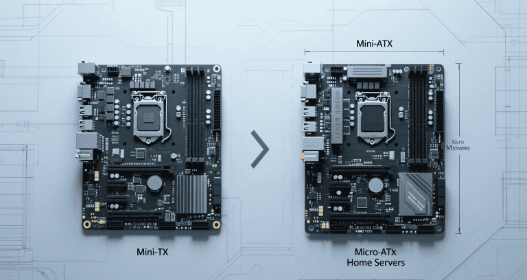
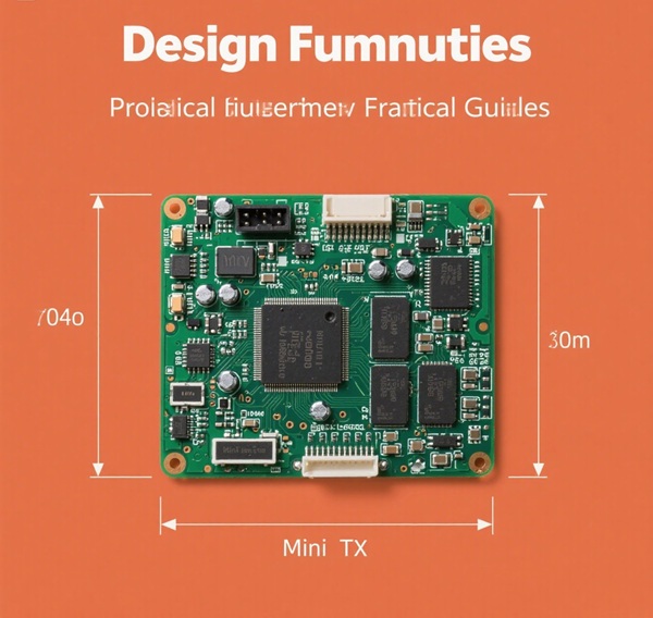
This section explains the physical and mechanical specifications that define Micro-ATX and Mini-ITX motherboards. Understanding these dimensions is essential before you attempt any cross-form-factor installation.
| Parameter | Micro-ATX Specification |
|---|---|
| Dimensions | 244 × 244 mm |
| Mounting Holes | 8 positions |
| PCIe Slots | Up to 4 |
| Parameter | Mini-ITX Specification |
|---|---|
| Dimensions | 170 × 170 mm |
| Mounting Holes | 4 positions |
| PCIe Slots | 1 (x16) |
Physically, a Micro-ATX board will overhang by 74 mm per side in a Mini-ITX case, misaligning standoffs and PCIe slot locations. This makes conventional mounting impossible without heavy modification.
In this section, I’ll walk you through how power connectors, VRMs, and power delivery differ between Micro-ATX and Mini-ITX designs, and why these differences matter in confined enclosures.
Micro-ATX boards place the 24-pin connector further to the right, often near the middle of the board, and the CPU EPS connector at the top edge. Mini-ITX cases assume these connectors are closer together.
| Board Type | Typical TDP Support |
|---|---|
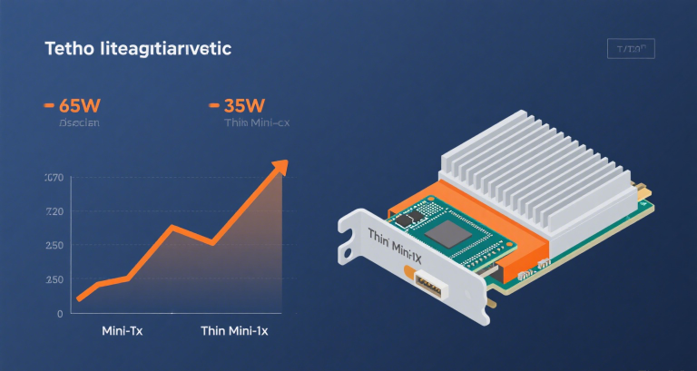
| Mini-ITX | 65–95 W |
| Micro-ATX | 95–150 W |
This section focuses on how airflow, CPU cooling, and GPU thermal loads interact with form factor constraints, which is often the main reason such builds fail in production.
Most Mini-ITX cases have CPU cooler clearances below 60 mm. Micro-ATX motherboards assume you can fit taller tower coolers (~120 mm).
“We tested a 95W CPU in a Mini-ITX chassis with a 37 mm cooler and saw sustained thermal throttling at 85°C.” — Senior Thermal Engineer, MiniITXBoard
Limited internal volume restricts exhaust pathways. High-power GPUs can quickly saturate internal air, increasing the risk of VRM overheating.
In this part, I compare the expansion capabilities of Micro-ATX versus Mini-ITX, including PCIe, M.2, and networking options, and explain the practical consequences of mismatched configurations.
| Feature | Mini-ITX | Micro-ATX |
|---|---|---|
| PCIe Slots | 1 x16 | Up to 4 |
| M.2 Slots | 1–2 | 2–3 |
Even if you install a Micro-ATX board, the Mini-ITX case physically blocks additional slots, negating any expandability gains.
Here, you’ll learn how I/O shield alignment and rear port accessibility impact installation and maintenance when combining Micro-ATX boards with Mini-ITX enclosures.
Mini-ITX enclosures expect a 170 mm-wide I/O area, causing misalignment:
Internal brackets and fans can block or partially cover ports, compromising usability and signal integrity.
This section covers practical issues such as cable management, component replacement, and how constrained space affects serviceability and reliability over time.
Mini-ITX cases have few tie-down points. Extra cables from a larger board can clog airflow paths.
Here, I’ll help you assess whether mixing form factors actually saves money when you factor in extra labor, cooling solutions, and potential rework costs.
| Item | Mini-ITX | Micro-ATX |
|---|---|---|
| Motherboard Cost | Higher per feature | Lower per feature |
| Case Cost | Higher per liter | More options |
Custom harnesses, additional cooling, and longer assembly time often erase any upfront savings.
This part details a structured approach to verifying mechanical fit and thermal performance before committing to production builds, helping you avoid expensive mistakes.
Prototype assembly is strongly recommended to confirm fit and validate thermal performance under load.
In this section, I outline certifications, environmental regulations, and testing standards that apply to embedded systems using mixed form factors.
Here, I share examples of cases and designs that intentionally support both form factors, offering more flexibility if you must combine Micro-ATX boards with compact enclosures.
Certain chassis have adjustable standoffs and backplates to fit multiple form factors.
Fractal Design Node 804 supports both Mini-ITX and Micro-ATX.
This section provides professional recommendations on choosing the right case or motherboard to achieve your goals without compromising performance or reliability.
| Feature | Mini-ITX | Micro-ATX |
|---|---|---|
| Expansion Slots | 1 | 4 |
| VRM Cooling | Limited | Better |
Mounting a Micro-ATX board in a Mini-ITX case is generally impractical due to mechanical, thermal, and electrical challenges.
“Always validate compatibility through CAD models and thermal simulation. Mismatched components rarely yield professional-grade reliability.” — Systems Architect, MiniITXBoard
For expert guidance and suitable components, visit MiniITXBoard.